Thursday, February 6, 2025

GE NAMING CONVENTION PART 1: A TALE OF THREE NEW SERIES AND THE DASH 8


A promotional GE paper depicting the C30-7A, a model unique to Conrail.
Note that this paper describes the locomotive as having 3100 horsepower.
  
    General Electric's locomotive catalog had a constantly changing, very comprehensive naming system designed to differentiate every model at a glance without having to see the model. Every part of their naming convention was specially designed to differentiate different models, and allow for simplicity of naming and discussion... Except for one example: the "New Series".

    "New Series" is a name GE used to describe not one, not two, but three different lines of locomotives built between 1976 and 1986. Worse still, sometimes GE's own numbering convention fails their equipment - see the above Conrail C30-7A having 3100 horsepower. In this post I hope to discuss all of the "New Series" by catalog and by model, to hopefully provide a differentiator between the three catalogs.

NEW SERIES - 1977

The admittedly undescriptive cover of a 1977 New Series operating manual.
 

    Despite being called the 1977 New Series, this line of locomotives was actually introduced in 1976. The 1977 New Series was a line of FRA clean cab complying replacements to the Universal line, including a handful of improvements to the ergonomics of the locomotive. Despite carbody changes and minor improvements across the board, these locomotives were largely identical to their Universal counterparts. Of note is that GE provided a direct replacement to every then-cataloged Universal in 1976.

4 AXLE

  • B18-7 (UNBUILT) - Direct replacement for the U18B. The only model in the entire domestic series other than the U18B and U18BT (unbuilt) to include the FDL8.
  • B23-7 - Direct replacement for the U23B. Used the FDL12.
  • B28-7 (UNBUILT) - A new model for this line. Would have used the FDL12.
  • B30-7 - Direct replacement for the U30B. Used the FDL16.
  • B33-7 (UNBUILT) - Direct replacement for the U33B. Would have used the FDL16.
  • B36-7 (UNBUILT)* - Direct replacement for the U36B. This is not the same locomotive as the B36-7 covered later on in this post. Would have used the FDL16.

*SSW's preproduction B36-7's technically count as original B36-7's as they are on the original 1977 revision 4 axle frame. I hesitate to call these New Series B36-7's largely due to their prototype status and otherwise functional identity as later B36-7's, however.

6 AXLE

  • C23-7 (UNBUILT) - Direct replacement for the U23C. Would have used the FDL12.
  • C28-7 (UNBUILT) - A new model for this line. Would have used the FDL12.
  • C30-7 - Direct replacement for the U30C. Used the FDL16.
  • C33-7 (UNBUILT) - Direct replacement for the U33C. Would have used the FDL16.
  • C36-7 - Direct replacement for the U36C. This is not the same locomotive as the C36-7 covered later on in this post. Used the FDL16; only ordered by NdeM and Hamersley Iron.

    The 1977 New Series was very comprehensive in its catalog, however the lack of deviation from standard horsepower brackets (the only 1977 New Series' built were B23-7's, B30-7's, and C30-7's) is apparent. Most railroads were purchasing line haul drag power in the C30-7 or road freight power in the B23-7 and B30-7. Do note the B36-7 and C36-7 in this line; they are functionally different from the later built models covered in the next section of this article, and the B28-7 and C28-7, both offered as more fuel efficient V12 models of the B30-7 and C30-7. While neither would be built, they would be iterated on further in the next catalog iteration in 1980.

NEW SERIES 7 - 1980

The cover of a 1980 revision Series 7 manual. Note the added 7 to the New Series moniker.

    The next catalog upgrade from GE came in 1980 with the "New Series 7". GE shortened the 1977 New Series name down to only the decade digit, differentiating these locomotives as 1970's designs. Unlike the 1977 New Series, New Series 7 actually included new models with major upgrades and improvements. GE also trimmed away the catalog down to only the most popular models.

4 AXLE

  • B23-7 - Carried over from the 1977 New Series catalog with no major changes. Used the FDL12.
  • B30-7A - A new model for this series. Intended to replace the B30-7, however both were offered concurrently. Used the FDL12.
  • B30-7 - Carried over from the 1977 New Series catalog with no major changes. Used the FDL16.
  • B36-7 - A new model for this series. Used the FDL16.

6 AXLE

  • C30-7A - A new model for this series. Intended to replace the C30-7, however both were offered concurrently. Used the FDL12.
  • C30-7 - Carried over from the 1977 New Series catalog with no major changes. Used the FDL16.
  • C36-7 - A new model for this series. Used the FDL16.

    GE's apparent laser focus with the New Series 7 into fuel efficiency and raw power seems apparent on paper, but is much more apparent in reality, as the horsepower numbers listed in these locomotives are very flexible depending on era. As an example, a C36-7 built in 1980 is most likely 3600 horsepower, however much later production units (such as Missouri Pacific's) are 3750. The 3000 horsepower V12 locomotives are descended from the unbuilt 2750 horsepower B28-7 and C28-7, and can be 3100 horsepower if ordered late enough.

    The new models in this catalog are unique in that they carry GE's GTA-24 alternator (with the exception of the C30-7A) and SENTRY creep control, allowing for greatly improved low speed performance. This is in stark contrast to the 1977 New Series' 3600 horsepower models, which would have used performance control and power reduction in place of advanced creep control.

NEW SERIES 8 - 1984

The cover of GE's Series 8 Handbook.

    The last catalog iteration to use the New Series moniker was the 1984 series, dubbed New Series 8. Very few people in enthusiast circles describe this series as such, however; the "Classic Dash 8" has stuck far better. Truthfully, Classic Dash 8 is a better descriptor, as these models are functionally proto-Dash 8's in technology and performance.

    It should be noted that, unlike the change between 1977 and 1980, the New Series 7 was still offered alongside the New Series 8. The last New Series 7's were built in 1986 (an order of C30-7's for NdeM), and although none were built beyond then, paper material suggests that they were still available as late as 1991.

4 AXLE

  • B23-8 (UNBUILT) - A direct replacement for the B23-7. Would have used the FDL12.
  • B32-8 - A direct replacement for the B30-7A. Used the FDL12.
  • B39-8 - A direct replacement for the B36-7. Used the FDL16.

6 AXLE

  • C32-8 - A direct replacement for the C30-7A. Used the FDL12.
  • C39-8 - A direct replacement for the C36-7. Used the FDL16.

    The catalog has been streamlined even further here, trimming away the V16 3000 horsepower offerings and totally replacing them with V12 equivalents. This line of locomotives are also the first to include GE's GMG series alternators, which would continue to be built by GE well into the era of the Evolution line.

    In early 1987, GE introduced an iterative upgrade to the New Series 8 which massively overhauled the carbody and made minor changes to the locomotive's internal layout. Despite the massive changes between 1986 production Series 8's and 1987 production Series 8's, GE did not differentiate between them. Enthusiast circles have dubbed these models as "Enhanced", placing an E at the end of their names, however these are not official. Only two models of Series 8 ever received "Enhanced" variants: B39-8's built for lease service to BN and the last NS order of C39-8's.

DASH 8 - 1987

GE promotional photograph of Conrail 6050, the class unit of their Dash 8-40CW fleet. Conrail classified these units as C40-8W.

    GE introduced the Series 8's replacement later in 1987, with the first Dash 8's appearing on the market. Direct replacements for all models (minus the B23-8) were immediately available, with the V16 equipped models receiving a minor horsepower increase to 4000. GE also introduced a new naming convention with this catalog, dropping New Series and replacing it with Dash and the decade of introduction (GE was already in the planning stages for the Dash 9 at the time of the Dash 8's introduction).

  • Dash 8-32B - A direct replacement for the B32-8. Used the FDL12.
  • Dash 8-40B - A direct replacement for the B39-8. Used the FDL16.
  • Dash 8-32C (UNBUILT) - A direct replacement for the C32-8. Would have used the FDL12.
  • Dash 8-40C - A direct replacement for the C39-8. Used the FDL16.

Widecab variants came later on, with the first widecab 6 axle appearing in 1989 for UP and the first widecab 4 axle appearing in 1990 for ATSF.

  • Dash 8-40BW - A widecab alternative to the Dash 8-40B.
  • Dash 8-40CW - A widecab alternative to the Dash 8-40C. 

Other special order models under the Dash 8 umbrella include:

  • Dash 8-32BWH - HEP equipped V12 powered 3200 horsepower widecab passenger locomotive. Special order for Amtrak.
  • Dash 8-40BP - The Genesis! Specifically the 4000 horsepower model. Also known as P40DC, GENESIS Type 1, and AMD-103. Special order for Amtrak.
  • Dash 8-42BP - The second generation Genesis. Also known as the P42DC and GENESIS Type II.
  • Dash 8-32BP-DM - Third rail capable AC traction motor equipped V12 powered 3200 horsepower Genesis. Also known as the P32AC-DM. Purchased by Amtrak and Metro-North.
  • Dash 8-40CM - Full width cowl carbody Dofasco high adhesion truck equipped Dash 8-40C. Made for the Canadian market; purchased by BC Rail and Canadian National. 

I originally omitted the P42DC from this list as I had not seen it referred to with a Dash 8 moniker. I have since been proven wrong; it is referred to as a Dash 8-42BP in parts manuals.

Much later in the life of the Dash 8, GE offered horsepower upgrades to 4135 horsepower instead of 4000, birthing the following models. The upgrade could also be done to previous Dash 8's.

  • Dash 8-41CW - Factory optional 4135 horsepower upgrade for the Dash 8-40CW. Purchased by ATSF and UP.
  • Dash 8-44CW - 4390 horsepower upgrade for the Dash 8-40CW. CSX exclusive. 

Beyond the Dash 8, GE's naming convention becomes muddy, and I hope to cover it in a future post. For now, though, enjoy this descriptive catalog of GE's diesel locomotives built between 1976 and 1993.

Tuesday, October 8, 2024

THREE PHASE MOTORS ON SINGLE PHASE SUPPLY: A MOCKERY OF INDUCTION

(This article was written by my friend, Laz. Thank you for writing this for my blog!)

hi i'm laz
Once again I have elected to write an alarmingly niche article about electrical equipment on a Diesel-focused blog.

Those aware of who I am regardless of from /where/ likely know that I have been working on a simulator, ever more complex than the last time I was "working on a simulator." Much like my prior article on an entirely unrelated bloggard, I have discovered dark and horrible things, and in the process perhaps disproved a "foamerism" - i.e. a myth that is typically incongruent with reality. More on that later.

Let's take a look at the kind of equipment in question here. 


Fig. 1: Norfolk and Western's L-C-1.

Fig. 2: Virginian's EL-1.

Fig. 3: PRR's FF-1.

A few things to note, beyond my obsession with jackshaft locomotives.
    - The motors themselves are massive, and jammed up into the frame
    - They're all boxcabs (Not relevant, but it's a sharp look)
    - They're all 1ϕ AC-collection, 3ϕ AC motor equipment.
    
    (hint: "ϕ" is your phase symbol)
    
That last item is where things get tricky. Equipment like the GG1 is, in the most technical of senses, AC drive; AC power is collected, where voltage is regulated via tap transfomer, and then in single phase format run through DC-style motors - usually referred to in documentation as "commutator motors". The upside of this format is the ridiculous simplicity. You lose some efficiency in exchange for not having to deal with some means of rectification (Especially in the 1930s, where the options are "Good luck" or "Lmao" if you don't have room for a massive motor-generator), or dealing with the quirks of DC distribution and collection (Further reading: Terrorizing M-G substation personnel on the MILW). The downside is you get all the downsides of DC and none of the upsides of AC, in terms of wheelslip control and motor performance. Single phase feed to true single phase induction motors is also a non-starter, as single phase induction motors tend to have issues with generating torque at 0 rpm and have other characteristics highly undesirable for railroad applications.

Fig. 4: The phase converter, as installed in the FF-1.

Fig. 5: The actual wiring diagram of the phase converter as installed
in the L-C-1. The actual operating theory is identical.

Fortunately (or not) in 1914 - when the N&W units were delivered - this was a solved problem with the recently invented Rotary Phase Converter. As far as concepts go, the device appears similar to a motor generator, except the "motor" part also contributes phaseulation to the actual traction circuts. This nets us true 3ϕ, though since it's not /actually/ a motor-generator set we cannot just vary excitation for load-side voltage control. Further, starting a locomotive by directly connecting the motors to knocked-down line voltage and frequency, and praying for the best through a (effectively) dead short connection at 0mph is, hopefully for obvious reasons, undesired. One has zero control over wheelslip or runout, and this leads to extremely poor train handling. This is a bit of a problem when you have hundreds of thousands of pounds of force available. There's a couple things we can do to mitigate this, fortunately. At least reversing the motors is simple enough - swap two leads, motor runs backwards. Simpler design than DC type setups. First off, the obvious one that gets brought up:

Fig. 6: Prints of the pole-changer device from the L-C-1. It's a two-position device that sets up connections from three-phase supply. Eight pole behaves like your low gear; four pole behaves like high gear.

Fig. 7: A diagram of motors #1 and #2 on same. Note the myraid of connections, feel free to match up letters with Fig 7. Worth noting that each married pair was not just a whole locomotive coupled; each set shared one phase converter.

All three locomotives above utilized pole-changing motors; note the connections halfway through each field. Using two different pole connections effectively gives you two "top speeds" - by changing the wiring configuration of the motors, you can select one of two top speeds on a fixed frequency. Both the N&W and VGN ran 14.3 and 28.6 mph, and the PRR unit ran 10.3 and 20.6. Above we see the Pole Changing Device (Each motor has one) and the motor itself, in a delta (Simulator namedrop? No way) wiring format. Two power notches, a top speed in the 10-28mph range depending on the exact configuration, we're getting better, but we still have untenable inrush current and a somewhat awkward motor force curve.

This answer was good enough for me for several years, but there's a better way. A more regulated way. A way with a secret, third handle: the actual throttle. 


Fig. 11: A diagrammatic top-down of the VGN EL-1 or 2 or 3 or whatever you like operating cab. Two handles for your brakes, then an Extra Surprise Handle for your viewing pleasure.

Fig. 10: The master controller from the FF-1. It was a miracle I got this photo and I wish I had it in higher quality; the upper handle is your "speed" handle. The lower - your accelerating handle. If you look closely you can see three positions in addition to the one the handle is presently at.

What could it /mean/?

So a funny thing: the "speed handle" is perhaps counterintuitively not a throttle at all. It is functionally a selector, with three major positions, and mechanically five positions. For the N&W and VGN equipment above, positions are: OFF, 8P, 8P-14MPH, 4P, 4P-28MPH; "P" designating "Pole", and typically referred to by railroads as a specific speed connection. In the OFF position, the pantographs cannot be raised and several other functions do not receive power, such as the sanders. By and large, intended operation is to operate the whole route in one speed connection as there's no disconnect logic for the pole changeover switch. So if you can't use the speed handle for anything other than what today's maximum speed will be, what's the third handle actually /do?/

Fig. 9: All three drums pictured - each device here is physically linked to a handle.

Essentially, it controls the acceleration selection drum. It's a four position handle in and of itself - RAISE, HOLD, LOWER and OFF. This acceleration drum drives a rheostatic control group, which drives a notching relay, which serves as a regulator for raising or lowering the effective fluid immersion for the liquid rheostats. It's like a nuclear reactor, except you bring the reactor to the fuel rods.

Fig. 12: Another cross section from the FF-1, illustrating the Liquid Rheostat tanks and arrangement. The spindly thingies - one per motor - in the orange are the actual conductors. The blue electrolyte is pumped up, and a higher level gives lower resistance; this gives a fail-safe, where any failure causes electrolyte to fall back to the holding tank and the resistors to return to an "open line" state.
 
Why use air-cooled multi-notched resistor banks (A la most DC equipment of this vintage) when you can have your resistor itself be the coolant, plus infinitely variable? Add more saltwater and you lower the resistance. Reduce, or raise the electrode out, and you raise the resistance. Obsolete now, but a very popular device up through the 1980s and capable of very high loads and high-capacity softstarts without a means for burnout, provided the liquid doesn't boil. The only real challenge is corrosion control. All three classes of locomotive above use the same design: speed handle is set-and-forget top speed plus power on or not, accelerating handle varies the rheostat immersion which, mind you, occupy a significant portion of carbody, which then allow you to vary line voltage supply to -

Wait, hang on.

Fig. 8: God Bless Wikimedia Commons. A diagram illustrating the somewhat unfavorable torque curve for a given supply frequency-amperage; note that as the motor accelerates, torque actually /drops/ before picking back up. If this sounds wonky and uncomfortable and Difficult To Handle, it's because it is.

So, first. Induction motors, in their typical "squirrel cage" format, have a rotor with coils shorted together - current, and consequently torque, is induced as the rotor then tries to chase the field to the limit of frequency. The actual force equation requires some big brain math much smarter people than me can explain, and which is outside the scope of this article. For the most part, though, to have any reasonable control over an induction motor you need to vary frequency with supply voltage, as induction motors are extremely sensitive to supply voltage changes. So what are these rheostats actually doing?

Fig. 13: Something's Wrong I Can Feel It. Typical "squirrel cage" induction motors have their coils shorted together - yet these are not only /not/ shorted, but all six rotor connections run out of the motor through slip rings, outways. What.

So, back to the motors themselves - these /are/ induction motors. Current is induced in the rotor, to net torque. Those connections back out of the motor require (several!) slip rings, which are another wear item - something you don't put in without a good reason. Another note about induction motors: If the rotor connections are open, rather than shorted, the rotor develops no torque even with a fully excited field. There's another effect - as you add resistance to the rotor coils, the maximum torque-speed (aka "breakdown torque") of the motor slides back to 0rpm - pretend the peak of the chart above moves leftways, and then moves past zero until eventually the line slides down to (0,0). If you have good control over this resistace, you not only have a soft starter, but actual graduated torque control without frequency or voltage manipulation. This here is what those rheostat banks vary, and don't "see" full line voltage at any point. The motor design in practice is what's known as a wound-rotor motor. By varying the resistance across the rotor coils, fine load control is accomplished.

Fig. 14: Here's a very rough and approximate chart I made up in desmos. Each axis is normalized to 0-1. X axis is RPM as a function of selected top speed (1 being 100%), Y axis is a function of your motor's absolute maximum torque (0-1, 100% being, well, full torque). The dotted red line is your "fully-on" torque-speed characteristic. Blue is marginal resistance, black is somewhat more, red is more, purple is more, orange is Even More - you can see how the line gets flatter and any given speed has less and less torque for more resistance.
 

So that's about all there is to it. Big Liz was not simply a three notch throttle, with Off/Half Go/All Go. The reputation for ripping cars in half is almost certainly undeserved; fine control over starting loads was possible which speaks more to poor handling than design flaw, and compared to her contemporaries isn't necessairly that overpowered. The VGN and N&W units often operated in three unit sets, netting /massively/ higher drawbar forces - and 50% more horsepower nominal - than the orphaned PRR example, and all three classes enjoyed long service lives of >20 years.

Monday, July 29, 2024

WHY THERE WAS NEVER AN SD30

A GP30. Craig Garver collection

    Those of you who know me from other communities online will know I am a staunch advocate against the conceptual SD30. But...why? Following the rest of EMD's catalog, both before and after the 30, EMD catalogued both 4 and 6 axle variants of every model, only deviating in the modern era with the general discontinuation of 4 axle road power in the 90's. So why no SD30? The short answer is that there was never an SD30, mostly due to company priorities at the time. The long answer is a wild tale about what the GP30 was, why it existed, and why there was no market for 6 axles at the time of its introduction.

 
UP 494 is typical of an average GP20. Craig Garver collection
    For starters: we need to discuss the GP20. EMD had been experimenting with turbocharging starting in 1956 with some experiments heralded by UP to produce turbocharged variants of the 16-567. Laboratory testing found 2400 horsepower was possible, however in order to transmit this horsepower to the ground they would need a much stronger traction motor capable of 600 horsepower; their current TM was only capable of about 500. As a stopgap they developed the GP20, which was downrated to only 2000 horsepower. At the same time, they offered the GP18 as a direct replacement for the GP9 in their catalog. Both units were produced starting in 1959. 

CB&Q 504 is a very well restored SD24. Of note is the high nose,
which CB&Q optioned over the low nose.
Ron Zack photo

    The horsepower restriction on the GP20 was unnecessary for 6 axles, as a 2400 horsepower 6 axle would only put 400 horsepower into each motor. EMD immediately offered the SD24 as their premier high horsepower 6 axle locomotive, readily competing with ALCO's RSD15. (They also offered the SD18 as a replacement for the SD9 which carried 1800 horsepower from a roots blown 567.) EMD's catalog in 1959 was as follows:

  • GP18 - Roots blown 16-567D1, 1800 HP
  • GP20 - Turbocharged 16-567D2, 2000 HP
  • SD18 - Roots blown 16-567D1, 1800 HP
  • SD24 - Turbocharged 16-567D3, 2400 HP

This catalog was almost competitive with ALCO, offering an equivalent to every locomotive in their lineup bar the RS27 (ALCO themselves produced the RS32 to directly compete with the GP20, equipped with a V12-251 making 2000 horsepower). But there was a new contender on the market at the same time, and they brought far more sinister competition than what ALCO was capable of...

    GE exploded out onto the market in 1960 with the U25, a 2500 horsepower 4 axle road switcher locomotive kitted out in GE's newest developments in railroad technology. Equipped with the sturdy GT-598 generator and GE's tried and true 752E traction motor, the U25 immediately lit a fire under EMD to produce something significantly more competitive in horsepower. Of note is that GE (in 1960) had no intention of producing a 6 axle equivalent to the U25, intending to sit on 4 axle power while they developed a 3000 horsepower road locomotive.

UP 634 was once GE 2502, one of a four unit set of production demonstrators turned
U25 demonstrator turned UP unit. Craig Garver collection

    EMD immediately returned to work to produce something to compete with the U25. While EMD was still the dominant force on the market, and ALCO was quickly sliding into obscurity compared to the GM giant, GE was a company large and capable enough to seriously challenge EMD's iron grip on the industry. EMD got to work to upgrade their traction motors and turned to their design department to create an attractive new carbody to replace the GP20's now ten year old hood and cab. EMD quickly introduced a minor upgrade to their traction motor and generator, producing what they dubbed at the time the GP22, with 2250 horsepower.

The GP22 was a stark departure from EMD's previous carbody. Note the large protrusion
which houses the dynamics, main air intake, and headlight.
EMD photo

    The first road capable GP22 was turned out in 1961. While it technically rode on the same frame as the earlier GP20, the carbody was massively redone with a raised engine hood, reoriented radiator, and a much bigger short hood. EMD marketing at the time also requested the renaming of the GP22 to have a higher number in its name than the U25. The expansive electrical cabinet necessitated the raising of a section of the hood, which GM's designers used to create the unique hood shape which defined what was now renamed to the GP30, touting "30 improvements over previous EMD locomotives." A few minor carbody upgrades were also given to the GP30 carbody prior to its introduction as a demonstrator, where it went off to compete with GE's now twelve strong U25 demonstrator fleet.

The same, previously unnumbered GP22, now updated and renamed to GP30. It was introduced
as a demonstrator in 1962, hence its number.
EMD photo

    SD24 production had tapered off significantly after 1960. Very few roads were interested in purchasing large fleets of locomotives in the early 1960's, and fewer were interested in more expensive 6 axle locomotives. The few customers of the SD24 were western roads in need of high tractive effort higher speed power for running freight over large mountain ranges (ATSF, CB&Q and UP) and the massively expanding Southern, in need of more road power for its growing network. By 1961, EMD was still offering the SD24, but nobody was biting. GE did not have any interest in making a 6 axle locomotive, thus EMD focused their efforts on attacking the U25 in its own market. 

Make no mistake, these are not SP units. EMD owned them wholesale, and wanted SP to buy them
and more in repeat orders. They were not successful.
EMD photo


    EMD continued to offer the SD24 nevertheless, and targeted SP as a possible customer of new SD24's in 1962 (SP had, conspicuously, been a debut purchaser of the U25). Producing a trio of full SP spec SD24's, paint and all, the three units were sent to SP for demonstrating. The trio ran on SP for several months, gathering data and attempting to sell to SP management. SP mechanical was not impressed with the SD24; while it was more fuel efficient than an SD9, it was only marginally more effective in tractive effort, and paled in comparison to SP's latest experiments in German built diesel hydraulics. SP ultimately turned down the SD24, and the three were sent back to EMD and sold to Union Pacific at a slight discount.

     The GP30 replaced the GP20 in EMD's catalog, and the latter was dismissed. It was always intended as a stopgap, and it had served its purpose by the time the improved GP30 arrived. EMD, however, decided dedicating time to develop a 6 axle GP30 was not worth the effort and money, mainly due to the failure of the SP SD24's and the lack of any major orders. EMD's catalog now lists as follows:

  • GP18 - Roots blown 16-567D1, 1800 HP
  • GP30 - Turbocharged 16-567D3*, 2250 HP
  • SD18 - Roots blown 16-567D1, 1800 HP
  • SD24 - Turbocharged 16-567D3, 2400 HP

*Although the GP30 carried the same 567 revision as the SD24, it was slightly detuned.

    While the GP30 was attractive from a marketing standpoint, it was inferior to the U25 in performance, which EMD knew and was fully intending to fix. By 1963 EMD was back to the drawing board, developing more upgrades to the generator and traction motors and simplifying the new carbody to compete better with GE. By now, GE's catalog had expanded to encompass the U25B (the former U25) and U25C, a 6 axle version of the U25B made at the request of Oroville Dam. Customers that may have otherwise bought SD24's began purchasing U25C's, such as L&N and CB&Q. By now, the chance to develop a 6 axle GP30 was too little, too late; GE had a 6 axle road locomotive that would effortlessly defeat it in performance. EMD focused their efforts on their new replacement line to reunify their 4 and 6 axle turbocharged offerings.

The last of her kind, the final made of an already rare breed. She sits alone, as it seemed she always
was, high in the mountains of Utah. Down the mountain, in the yards in Salt Lake City, her sisters
once worked for UP; by the time of this picture in 1984, she is truly alone. But here, despite her
uniquity and the rest of the world passing her by, she toils away, doing what she was made to do.
Don Strack photo

    It is here where something very curious happens, and something often cited in discussions of 6 axle GP30's. Kennecott Mining Company, a large mining installation based out of Utah, came to EMD with a request for a locomotive. KMC needed a locomotive to service their Magna smelter, and were not interested in electrics. Magna sits high on the plains of Utah, at 4,000 feet elevation, and KMC was concerned about a roots blown locomotive being too weak in high elevation for their work, and thus requested a 6 axle turbocharged locomotive. EMD responded with an SD24 in 1963, numbered KMC 904. It was truly bone stock, carrying no optional extras other than dynamic brakes. 904 would be the final SD24 built. KMC did not purchase an SD30. They sent a request to EMD, which was filled with an SD24 by EMD themselves.


On display at the 1964 New York World's Fair, EMD 1964, one of the GP35 demonstrators,
rests outside GM's display.
Chuck Zeiler photo


    In 1964, EMD's upgraded carbody improvements were introduced with what was now called the 35 line. EMD matched GE's horsepower threshold with the 2500 horsepower GP35 and now introduced a 2500 horsepower 6 axle dubbed the SD35. Roots blown equivalents were also offered in the GP28 and SD28, but both were mechanically identical to the GP18 and SD18 outside of name and carbody. EMD had finally unified the 4 and 6 axle locomotives under one common carbody and horsepower rating, four years after they first split. The GP30 and SD24 were discontinued in favor of their 35 equivalents. EMD's catalog was then remade as follows:

  • GP28 - Roots blown 16-567D1, 1800 HP
  • GP35 - Turbocharged 16-567D3A, 2500 HP
  • SD28 - Roots blown 16-567D1, 1800 HP
  • SD35 - Turbocharged 16-567D3A, 2500 HP 

  It should be apparent by now that the introduction of the U25 caused a lot of trouble for EMD's catalog. The split between the 4 and 6 axle turbocharged locomotives that occured in 1960 that was not amended until 1964 was largely due to the advent of the U25 and the threat it placed on EMD at the time. Their direct competitor to the U25, the GP30, was a stopgap model made to immediately compete with the U25 instead of be a standardized offering in their catalog. The SD24, which was not outdated electrically and horsepower wise but was not standard physically, went unreplaced in EMD's catalog despite the development of the GP30 largely due to a severe lack of major orders. The SD35 was much more successful than the SD24, producing a respectable 360 total. 4 axles were still outselling 6 axles by a large margin, although the seeds of change were planted, paving the way for the SD40 and SD45.

A C&O SD35. The radical departure from the carbody of the SD24 is partially deceptive;
the two models have the same length frame and were not far from each other in
performance and electrical gear.

    Thus, no SD30. There was no 6 axle market during the lifetime of the GP30 which would warrant having one to begin with. What's more, the SD24 still made competitive horsepower and had yet to leave the catalog, so any prospective 6 axle purchasers could simply buy SD24's. An SD30 would not provide any meaningful upgrades to the 6 axle frame aside from standardizing an already experimental carbody on an outdated frame. This is why EMD opted to revise the frame for the 35 series, bringing the standard SD35 which was largely identical to the GP35. Alas, for GP30 fans, there was no 6 axle version offered, although the reality of EMD's catalog is somehow stranger than fiction.

    (In 2013, EMD produced an upgraded SD40-2 with a new cab and carbody for CP Rail which they named the SD30C-ECO. This model shares nothing with the aforementioned nonexistent SD30 and does, in fact, exist.)

Tuesday, May 28, 2024

CREATURES FROM ERIE: THE STORY OF GE DEMONSTRATORS 606 AND 607

   Today's blog post is a very very long one. While this story is mostly about two locomotives, to understand what became of both, I had to explain what GE was experimenting with around almost every turn over twenty years. I hope it makes at least some sense...!

    In 1980, GE debuted their revised B36-7 and C36-7 and introduced the B30-7A and C30-7A, which carried SENTRY wheel slip control and various minor upgrades to the carbody GE wanted to release. While the revised Series 7 (as the 1976 "New Series" had come to be known) were competitive with EMD's contemporary 50 Series, GE had bigger plans to revise their carbody with various improvements gathered through customer commentary as well as some iterative upgrades to GE's electrical gear and the FDL. These upgrades resulted in the construction of two very unique diesel locomotives: the 4 axle B36-8 606 and 6 axle C36-8 607 came out of Erie in mid-1982 and early-1983 respectively.

606 is teamed up with a dynamometer car and is
performing tests on what is likely the BN.
Photo from the collection of Paul Amos


    Clad in a brand new GE designed blue and white paint scheme, 606 and 607 were physically very different from GE's catalog at that point, equipped with hard edged carbodies and a much bigger short hood. GE also, for the first time since 1966, revised their cab design to provide more headroom while inside. Both units were equipped with electrically blown dynamic brakes, more expansive radiator cores, and an improved central air intake.They were identical mechanically and electrically, both boasting new 7FDL16J engines and 3750 horsepower (as were B36-7's and C36-7's built at that time) through GE's GMG187 alternator. (Some parts sources have referred to the GMG187 as the GTA187, however I have yet to nail down exact part numbers.) 

Photo credit Willie Brown

    SENTRY wheelslip control (GE's answer to EMD's Super Series wheel creep) had become standard with the second generation Series 7, and the demonstrator duo carried it as well. Both units were sent out to various owners of previous Series 7 locomotives with the intent of generating new orders for what GE was dubbing New Series 8. 606 was sent to various 4 axle GE owners, such as the Burlington Northern, for trial and testing. GE's Gemini dynamometer car followed 606 on most of its quests outside the test track at Erie. A demonstration trip on the newly formed Seaboard System (later CSX) led SBD to, ironically, buy a large order of B36-7's in 1985. 607 was sent off to newly formed Norfolk Southern, whose predecessor N&W had been the biggest stateside customer of the C36-7 up to that point, with a new order of C36-7's already in production at Erie.

606 on the BN in Washington. GE was never quite able to nail down why BN bought so many
B30-7A's, and despite the efforts of
606 (and the three B32-8's delivered to BN in full
BN spec/paint a year later)
, GE would have to lease B39-8's to BN to even get them
to operate any new GE product.

    606 and 607 returned to Erie to be upgraded with 3900 horsepower, being relabeled as B39-8 and C39-8 respectively. GE produced more Series 8's to go with them, making units in full railroad spec as demonstrators for specific roads. GE built three B39-8's in ATSF paint for the road to trial, made two C39-8's for NS to test, and produced a trio of V12 equipped B32-8's for BN. All eight units were sent off to their respective roads, with the intent being that the customer would purchase them at the end of the trial (GE had done this before with the U28B). Conrail, at the same time, came to GE with a 10 unit order for C30-7A's, which GE offered to replace with an equal number of new C32-8's. Conrail accepted the offer, making them the first Series 8 customer.

Don't be fooled by the paint; every locomotive in this consist is owned by GE. While they were in full
Cascade Green and carried full BN spec, GE owned 5497, 5498, and 5499 (and, of course, dynamometer car 100).

    The railroad spec units had varying degrees of success. Both BN and ATSF declined their demonstrators; ATSF's next GE purchase would be Dash 8-40B's in 1988 and BN would go on to lease a large number of B39-8's from GE owned LMX. NS, however, was sufficiently impressed enough with the Series 8 to buy both demonstrators and load up Erie with orders for more. NS would end up with the lions share of Series 8's produced, with 139 C39-8's. Conrail was not impressed with the reliability of the C32-8's, however they later purchased a single 22 unit order of C39-8's which were much more successful.

NS 8550 was one of two units made on GE's dime for demonstration on the NS. It was
identical in specification to the rest of NS' C39-8's aside from its control setup: it was
short hood forward. All other NS C39-8's were long hood forward.
Photo credit JL Scott


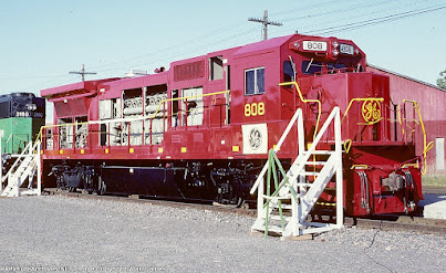
    606 and 607 spent a few years as warranty test units, going out in place of downed Series 7 units around the US, before coming home to Erie to be brought under the knife again. While most railroads were thoroughly impressed by the performance of the Series 8, they were very unhappy with the operating comfort. Complaints arose from mechanics and crews alike about their cramped cabs and tight hood clearances, and commented on how hard it was to get to various systems inside the carbody. GE elected to fix these issues, and bring new improvements to the Series 8 in a large upgrade. GE chose 606 to be the catalyst for these new improvements, and 606 emerged from Erie in 1986 as 808, clad in a brand new carbody with moved and improved subsystems and a much more spacious cab. 607, unlike 606, did not receive nearly as much of an upgrade, being made into a standard C39-8 and getting sent back to warranty coverage service.


The freshly rechristened 808 appeared at Galesburg Railroad
Days in 1986. While the carbody looks very familiar to the
future Dash 8, the cab is completely unique
to this one locomotive. Photo credit Alan Gaines
    The newly rebuilt 808 was sent out as a demonstrator again, being shown to various roads as the premier choice for fast freight power. While still classed as a B39-8, 808 differed greatly from all the other Series 8 locomotives produced up to that point, both physically and mechanically; GE was planning another uprating to bring the Series 8 to 4000 horsepower and was planning accordingly. One complaint on NS was that their C39-8 demonstrators were short hood forward, so to keep the possible customers interested 808 was equipped with dual control stands to allow the unit to be operated from either direction (one of the last locomotives in North America to be built with dual control stands). 808 demonstrated on the NYSW, generating an order for the Series 8's replacement Dash 8-40B. It returned to warranty service, where it spent more time on other roads. 

A C39-8, C36-7, and GE 808 lead a train on the Norfolk Southern. 808 is likely
providing warranty coverage for a B30-7A in this photo. Photo credit Sam Beck

    In 1987, the changes 808 brought to the Series 8 were introduced to GE's catalog, and the Dash 8 was properly introduced. The B39-8 and C39-8 were replaced by the upgraded and uprated Dash 8-40B and Dash 8-40C respectively, both of which did significantly better in sales; the Series 8 was discontinued. From here, things get very strange.


By now, 607 has become a standard C39-8. Here it is
in warranty coverage service on the NS.
Photo credit Paul Amos

    607 bummed around the United States as an otherwise normal C39-8 in warranty coverage service until 1988, when GE purchased MLW from Bombardier and got the rights to Dofasco's high adhesion 3 axle truck. GE intended to make inroads in the Canadian market, and were interested in trade in capability with older MLW products. 607 was rebuilt to ride on the truck for a brief period of time (while still being in warranty coverage service), gathering data for GE about the performance of the truck on a road locomotive. (Remember this, it will be important later!) It was made obsolete as a demonstrator when GE arranged to take one unit out of a completed UP Dash 8-40C order (they arbitrarily took UP 9185, with the unit becoming GE 001) and 607 was set aside at Erie. The data gathered by 607 while it carried the Dofasco trucks directly led GE to produce the Dash 8-40CM, formally introducing General Electric road locomotives to the Canadian market.

    The FRA had been discussing the introduction of improved cab construction safety guidelines, and wanted the manufacturers to introduce a new, much safer cab for their road locomotives. EMD looked to their Canadian produced GMDD cab design to produce what would become the SD60M. GE turned to MLW and their safety cabs, preparing their own improved design to introduce to the market. To produce a new safety cab demonstrator, GE returned to their now Dash 8 demonstrator 808 and sent it under the knife again in 1988, emerging as GE 809 with a completely unique "widecab" and 4000 horsepower. At the same time, one of Conrail's C32-8's (6612) was wrecked and its cab was destroyed; GE sent the cab of 808 to Conrail's Juniata shops to repair the unit with. 6612 carried the prototype GE improved standard cab until it was scrapped in the 2000's.

809 is shown here, newly rebuilt, doing crew evaluation on the Union Pacific.
Most of 809's demonstration was to get commentary on the widecab; what GE
learned from 809's demonstration time led them to create the widecab that the
rest of their catalog carried to this day.
Photo credit Bill Wilcox

    809 continued its tour de force around the US demonstrating the benefits of the safety cab to various railroads and their crews. While 4 axle diesel locomotives were all but dead as road power (barring ATSF's one off orders of the Dash 8-40BW), 809 generated orders for GE's improved Dash 8-40CW safety cab locomotive and demonstrated the benefits of the widecab over the standard "spartan" cab. It was set aside as a demonstrator in 1994 with the introduction of the Dash 9 and discontinuation of the Dash 8.

809 leads a train of Dash 8-40C's on the UP. These runs directly led to UP ordering
the first GE widecabs with the Dash 8-40CW.
Photo credit Tom Ellis

The last 4 axle product of Erie, PA rumbles past Sugar Creek,
MO with a TOFC train. Photo credit Flickr user Sneebly

    GE still had more in store for the duo. Further upgrades for the Dash 8 line included higher horsepower with a minor increase to 4135 horsepower being offered as an optional extra on Dash 8 orders after 1991, with ATSF, UP, and CNW all taking orders. GE continued to hammer away at the FDL and GMG while producing more and more Dash 8's of various type; GE produced their last 4 axle road diesel locomotive to this day with ATSF Dash 8-40BW 582.


    While the Dash 8 was selling well, and customers were very pleased with their performance, EMD appeared out of the woodwork in 1992 with a very threatening proposition: a joint venture with Siemens had brought about the SD60MAC, an AC traction motor equipped locomotive which brought highly increased tractive effort and longer motor life compared to a similar DC motor. Meeting the demand, GE once again turned to their MLW stockpile, procuring information about AC traction gathered from Canadian Pacific 4744, the lone M640, after it was rebuilt with Brown-Boveri AC traction gear. Laboratories at Erie began to piece together what would become the GEB13 AC traction motor, high adhesion truck, and radial truck (with the trucks being derived from the Dofasco high adhesion truck and its specifications, which GE had data on thanks to 607!).

Three of the four SD60MAC demonstrators
hustle a Soo Line freight through Iowa.
Photo credit Mike Danneman
 

    607, by now very out of date and almost fully replaced by GE's Super 7 in warranty coverage service, had mostly been gathering dust at Erie after GE had completed their testing of the Dofasco high adhesion truck. At the same time, the Department of Energy had been working with GE to produce experimental coal burning internal combustion engine technology, which used pulverized coal and petroleum to produce a slurry capable of being burned roughly similar to diesel fuel. 

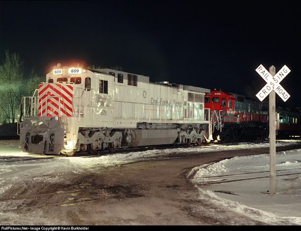
GECX 609 waits at the NS interchange near Erie to be sent for testing on Norfolk Southern.
Photo credit Kevin Burkholder


    Norfolk Southern, a major customer of both coal in the South and GE's road locomotives, partnered with GE and the DOE to bring the coal slurry tech to the railroads, with the intent of eventually making a coal burning diesel locomotive. The project came to fruition in 1994 when 607 was rebuilt into GE 609, dubbed the C39-8CF. The unit did demonstration on the DOT's Pueblo test track and GE's Erie testing trackage, burning pulverized coal and making rated horsepower. Unfortunately for the partnership, the coal slurry, with its consistency roughly equivalent to liquid sandpaper, led to extreme premature injector wear with the unit requiring extremely frequent injector replacement; NS backed out of the partnership after a few months. 609 lay unused at Erie for a year in storage once again, the "coal fueled diesel" experiment being deemed a failure.

609, the Coal Fueled Diesel, on the test track at Erie. Despite it's  many internal changes,
it was externally very similar to a normal C39-8. Note the air intake and dynamics,
which have been upgraded to those on the Dash 8.
...Hey, that's a Super 7 back there!

    With more customer feedback and technological improvements on the way, GE prepared another catalog upgrade, and built a demonstrator AC traction locomotive numbered 4400 (renumbered from 2000). The upgrades produced for what was now dubbed the AC4400CW (a stark departure from GE's naming convention of the last generation) were brought to DC traction as well, and GE created the Dash 9-44CW. Deeming a demonstrator unnecessary (GE by this point did most of their demonstration with already completed units from other railroads), the first Dash 9-44CW rolled out of Erie in a brand new paint scheme as a publicity event (the unit, 8601, was actually the first unit in a CNW order and was immediately thereafter repainted into CNW).


GECX 4400 at rest at Erie. This unit occasionally comes out for testing, and was
exceptionally common during testing of Evolution AC units.
Note the trucks; GE was planning to use the Dofasco hi-ad truck, but chose
to make their own with some improvements.
Photo credit Garth McMains


899 is shown here attached to an ES44 doing
altitude tests in Colorado.
The sticker on the nose of 899 states
that this unit is a "C44-9", a class
unique entirely to 899.
Photo credit Kevin Morgan

    Orders for the brand new Dash 9-44CW's and AC4400CW's began to flood in beginning in 1994. Orders by the hundreds from newly merged and power hungry railroads across the United States (and Canada) filled Erie's shop floor to the gills. GE elected to do further testing of the Dash 9 (and, by proxy, the AC4400CW) and its associated technology by building a "laboratory control group unit" which would function roughly identically to a Dash 9. Unable to make the space to produce an entire Dash 9-44CW that would see very infrequent use, GE pulled 609 out of storage and sent it back under the knife once more. The unit emerged with a full Dash 9 hood, an uprating to 4400 horsepower, and another renumbering to 899. The unit was mostly confined to Erie, doing bench testing alongside the AC4400CW and later AC6000CW, however it occasionally ventured outside the plant to be used for high altitude testing or rare bursts of short term warranty coverage.

899, now a strange chimera of a Series 8 and a Dash 9, rests in Montreal. Note that the entire
hood has been replaced with a Dash 9 hood, however the cab and nose remain from its
time as a C39-8.
Photo credit Eric Aucoin


    GE finally stopped rebuilding the duo after the mid-1990's. 899 continued to be used as a benchmark against the AC line throughout the 1990's, and was used again as a benchmark to compare the performance of the new Evolution line introduced in 2004. 809, meanwhile, saw static testing at Erie and was used occasionally for load testing, however it was most useful after it had its rear coupler replaced with buffer and chain connections in 2009 to accommodate testing new PowerHaul locomotives for export at Erie. Both units were non-operational starting in 2016, and today only 809 moves regularly around Erie for moving and road testing PowerHauls. 899 rests in the spare equipment pile at Erie, joined by Dash 8's, Dash 9's, SD40-2's, and other GE demonstrators in long term storage out of the way, occasionally appearing as a buffer car during tests.

809 rests with 832 (the Dash 8-32B demonstrator) and 001
(the Dash 8-40C demonstrator) at the temporary storage
area of Erie. Seen in the background are the AC6000CW
demonstrators at the final assembly building.
Photo credit Paul Duda
    It's hard to believe that, when they rolled out of Erie, 606 and 607 would live the lives they did. 606 was a pioneer for GE in technology and safety gear while 607 was present for the service tests of GE's most successful locomotive designs of all time. Both units are survivors in their own right; 899 is one of two Series 8 6 axles left in the United States (the other, Pennsylvania Northeastern 8212, is the only true C39-8 left in North America) while 809 is intrinsically unique by nature of its cab and multiple rebuilds. Their fascinating tale is so intricately weaved into everything General Electric was doing with their catalog throughout their existence that I hope both of them are preserved in museums for future generations to marvel at their uniquity and importance in producing the most influential locomotives of the modern era. And, despite their age, obsolescence, and non-functional status, they both still somehow find a way to see new technology being developed at their birthplace.

GE NAMING CONVENTION PART 1: A TALE OF THREE NEW SERIES AND THE DASH 8

     A promotional GE paper depicting the C30-7A, a model unique to Conrail. Note that this paper describes the locomotive as having 3100 ho...